Week 9 - Machine Design
The assignment this week was to design a machine. The Harvard Section met up initially Wednesday evening and decided on a UV art printer. To do this, we broke up into 3 teams: machining, programming, and assembly. The machining team would come in first and make all the carve paths and parts. Programming would come in a few days later and program the image to path on G-Code, movement in X and Y direction, and light actuation. Lastly, the assembly team would come in to wire, put the pieces together, and troubleshoot.
I joined the machining team since I felt the most confident in my milling skills.
Designing Carvepath
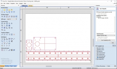
First part of machining was making the carvepaths. I initially thought that this would be simple since we were going to use mostly Jake's parts. I thought I could simply export the vectors from Rhino into V-Carve.
What I realized after was that we had to look in other dimensions to determine the thickness of the carve paths. We also had to think through other variables such as profile v. pocket cut (pocket cut for holes and profile cuts to make outlines); inside v. outside cut; bit to use (1/4, 1/8, 1/16, chamfer); crossover percentage; feed rate; and thickness depending on material (Delrin plastic v. polyethylene). It was also important to streamline the process such that you're not continuously changing the bits and rezero-ing the z-axis, but also that you're cutting components in an appropriate order.
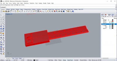
I first worked with Rob and Yanru to make the carve paths for the chamfered arm, which involved drawing a line that was offset from the actual component because the chamfer edge was 45 degrees and if the chamfer came down on the edge of the component, it would cut in too much. I then took the lead in making the carve paths of the rack rails components, which took significantly more time than expected since we had to use 4 different bits. Here is the V-Carve of the rack rail components with 8 different carve paths. The 8 carve paths are slider holes, countersinks, motor holes, big holes for parts holding the motor, initial toothpocket with 1/4", teethcleaning with 1/16", outside, and chamfer.
Machining
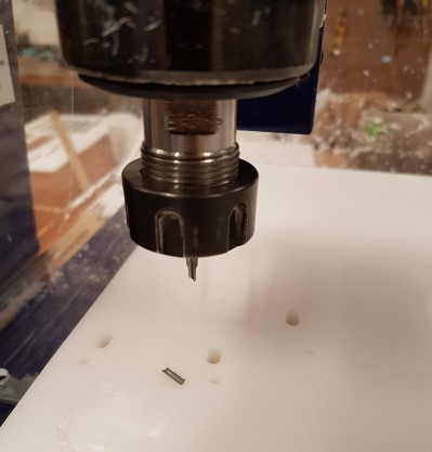
The machining began seemlessly. I learnt how to change the bit, and the following components were cut without much trouble. Instead of making tabs, we would mill the holes first, then screwed the parts down.
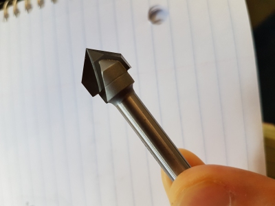
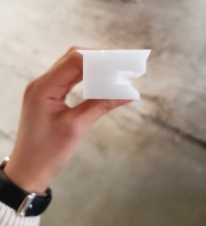
This is the chamfer that we used.
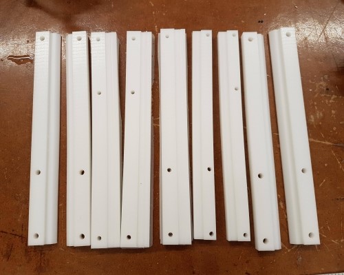
Here are the chamfered parts that Yanru and I cut, along with the unchamfered parts that Lily and Kevin cut.
Here is how the pieces that Yanru and I cut would fit with the pieces that Lily and Kevin cut.
When I began milling the rail rack components though, the 1/8" bit broke. When we checked back on the carve path, we realized that the feed rate was set at 3 inches/sec. That feed rate must have been too high for the bit, so I modified all the carve path feed rates to be 1 inches/sec just in case. Some of our feed rates were set at 2inches/sec, but I didn't want to risk breaking another bit.
After fixing the carvepaths and changing the bit, we continued to cut the rail rack components.
Tapping
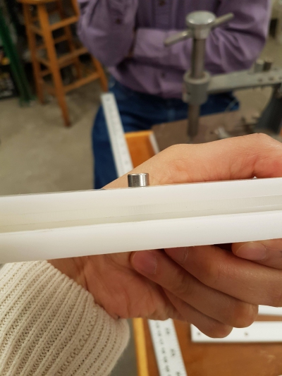
Rob also taught how us to tap. I learnt that tapping creates threads for screws to hold the pieces together. So, the top component would have a through-hole that would not be tapped, and the second piece would have a tapped hole that the screws can lock onto.
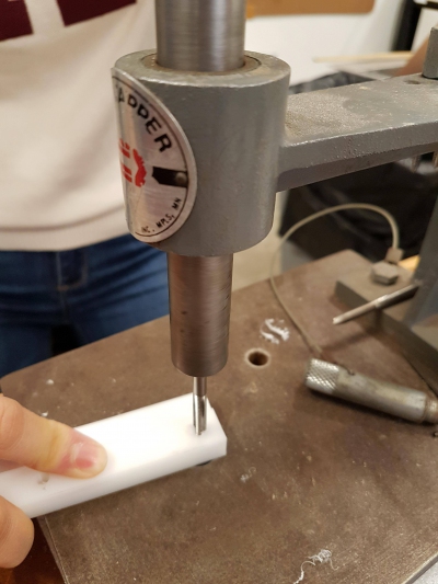
Here are the two pieces held together tightly after tapping!
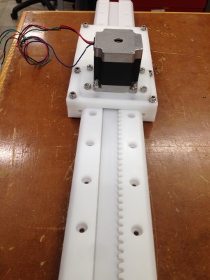
Final Product
Here is our final product!
Thanks to Rob and the Harvard section!
I also finally realized why my directory size was so big. I was compressing all my images and videos, but I left my uncompressed files in the same folder. I mistakenly thought that as long as I do not reference the uncompressed files, it does not matter. But, it turns out the entire folder is committed. My apologizes for having uploaded so many files onto the repository!!